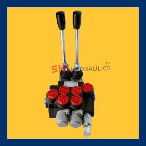
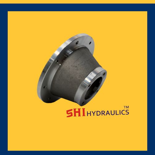
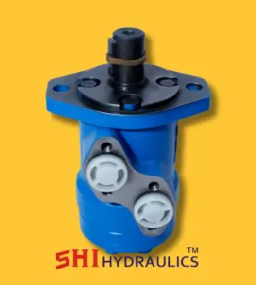
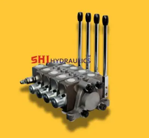
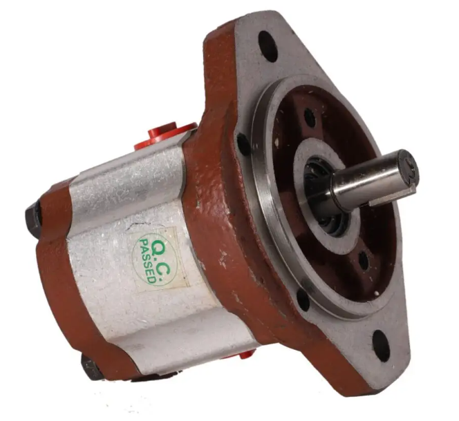
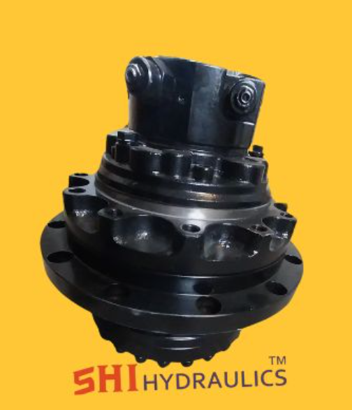
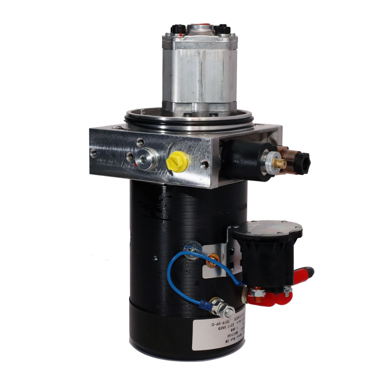
New Delhi
08045134631
+919311288288

Products

68179d65be22ee500d53ff54 Card 2

product image
manufacturer and tools

A control valve is a mechanical device used to regulate the flow, pressure, temperature, or level of a fluid (liquid, gas, or steam) within a system. It operates by varying the size of the flow passage in response to a control signal, ensuring precise process control in industries such as oil & gas, power generation, water treatment, and manufacturing. Key Components of a Control Valve Valve Body – The main casing that houses the internal components and provides a passage for fluid flow. Actuator – The mechanism (pneumatic, electric, or hydraulic) that moves the valve to adjust flow. Valve Plug or Disc – The movable part that regulates the flow by opening, closing, or throttling the passage. Stem – Connects the actuator to the valve plug for movement control. Positioner (Optional) – Ensures precise control by adjusting the actuator’s position based on control signals. Types of Control Valves Globe Valve – Provides accurate flow control with a linear motion plug. Ball Valve – Uses a rotating ball with a hole to control fluid flow, offering quick shut-off. Butterfly Valve – Features a rotating disc for efficient flow regulation in large pipes. Diaphragm Valve – Utilizes a flexible diaphragm to control flow, ideal for corrosive fluids. Needle Valve – Designed for fine flow adjustments in small-diameter pipelines. Pressure Relief Valve – Prevents overpressure by releasing excess fluid when necessary. Common Applications Industrial Process Control – Regulates flow and pressure in chemical, power, and manufacturing plants. Water Treatment – Controls water distribution and filtration processes. Oil & Gas Industry – Used in pipelines, refineries, and offshore drilling operations. HVAC Systems – Manages heating, cooling, and ventilation flow rates. Pharmaceutical & Food Processing – Ensures precise flow control for hygiene and efficiency.

68179d65be22ee500d53ff54 Card 2

product image
manufacturer and tools

A hose sleeve is a protective covering designed to shield hoses from external damage, abrasion, heat, and environmental factors. It enhances the durability and safety of hydraulic, pneumatic, and industrial hoses used in various applications. Key Features of a Hose Sleeve Abrasion Resistance – Prevents wear and tear caused by friction, rough surfaces, or other hoses. Heat Protection – Some sleeves are made of heat-resistant materials to protect hoses from extreme temperatures. Flexibility – Allows hoses to bend and move while maintaining protection. Chemical and UV Resistance – Shields hoses from chemicals, oil, water, and UV radiation. Easy Installation – Can be wrapped around existing hoses or slid onto hoses during assembly. Enhanced Safety – Helps prevent hose bursts, reducing the risk of injury and equipment damage. Common Types of Hose Sleeves Textile Hose Sleeves – Made from woven nylon or polyester for lightweight and flexible protection. Spiral Hose Sleeves – Durable plastic or rubber spiral wrap for impact resistance and bundling multiple hoses. Heat-Resistant Hose Sleeves – Fiberglass or silicone-coated sleeves for high-temperature applications. Fire-Resistant Hose Sleeves – Designed to withstand fire and extreme heat exposure. Common Applications Hydraulic and Pneumatic Systems – Protects hoses in heavy machinery and industrial equipment. Automotive and Aerospace – Used in fuel and brake lines to prevent abrasion and heat damage. Construction and Agriculture – Shields hoses from harsh environments and debris. Oil & Gas Industry – Protects high-pressure hoses from extreme conditions and chemicals.

68179d65be22ee500d53ff54 Card 2

product image
manufacturer and tools

A wire rope is a strong, flexible, and durable cable made from multiple strands of steel or other metal wires twisted together around a central core. It is widely used for lifting, hoisting, towing, and securing heavy loads in industries such as construction, marine, mining, and transportation. Components of Wire Rope Wires – Individual metal strands, typically made of steel or stainless steel, providing strength and flexibility. Strands – Groups of wires twisted together to form the rope’s outer structure. Core – The central support structure, which can be made of fiber (for flexibility), steel (for strength), or synthetic materials. Key Features High Strength – Capable of handling heavy loads and high-tension applications. Flexibility – Designed to bend around pulleys and sheaves without breaking. Abrasion Resistance – Some ropes are galvanized or coated for extra protection against wear and corrosion. Fatigue Resistance – Engineered to withstand repeated bending and stress. Common Types of Wire Rope Galvanized Wire Rope – Coated with zinc for corrosion resistance. Stainless Steel Wire Rope – Highly resistant to rust, ideal for marine and chemical environments. Compacted Wire Rope – Stronger and smoother due to compressed strands. Rotation-Resistant Wire Rope – Designed for lifting applications where load twisting must be minimized. Common Applications Cranes and Hoists – Used in construction and industrial lifting. Marine and Fishing – Essential for ship rigging, mooring, and trawling. Mining and Oil Industry – Used for drilling, winches, and lifting equipment. Bridges and Suspension Systems – Provides structural support in suspension bridges and cable-stayed structures.

68179d65be22ee500d53ff54 Card 2

product image
manufacturer and tools

Concrete Hose Description A concrete hose is a heavy-duty, flexible hose designed for transporting and placing concrete in construction projects. It is commonly used with concrete pumps to deliver wet concrete to hard-to-reach areas, such as high-rise buildings, foundations, and tunnels. Features of a Concrete Hose Durability – Made of reinforced rubber or synthetic materials to withstand high-pressure pumping and abrasive concrete mixtures. Flexibility – Allows easy maneuverability around job sites for precise concrete placement. High-Pressure Resistance – Designed to handle the high pressures generated by concrete pumps. Abrasion Resistance – Inner lining is typically made of wear-resistant rubber to withstand continuous flow of rough materials. Steel or Textile Reinforcement – Some hoses are reinforced with steel wire or textile braids for added strength and longevity. Various Sizes and Lengths – Available in different diameters and lengths to suit different pumping applications. Common Applications Building Foundations – Used to deliver concrete to deep and narrow spaces. High-Rise Construction – Essential for pumping concrete to upper floors. Tunnels and Bridges – Helps in pouring concrete in challenging locations. Road Construction – Used for pouring concrete in pavements and highways.

68179d65be22ee500d53ff54 Card 2

product image
manufacturer and tools

A bell housing is a protective casing that connects an engine to a transmission, enclosing the flywheel and clutch assembly (in manual transmissions) or the torque converter (in automatic transmissions). It is typically made of aluminum or cast iron and is shaped like a bell, hence the name. Functions of a Bell Housing Structural Connection – Provides a secure attachment between the engine and transmission. Protection – Shields internal components like the flywheel, clutch, or torque converter from damage and contaminants. Alignment – Ensures proper positioning of the engine and transmission for smooth operation. Noise Reduction – Helps in dampening vibrations and noise from the drivetrain. Mounting Point – Often has provisions for starter motor installation and other components. Common Applications Automobiles – Found in both manual and automatic vehicles. Heavy Machinery – Used in construction and agricultural equipment. Marine and Industrial Applications – Protects drivetrain components in boats and stationary engines.

68179d65be22ee500d53ff54 Card 2

product image
manufacturer and tools

HDD Gear Pump HDD Gear Pump Overview (Hydraulic Driven Displacement) are widely used in industrial applications, primarily in hydraulic systems, due to their durability, efficiency, and ability to handle high-pressure environments. These pumps are a type of positive displacement pump, and their design ensures the consistent flow of fluid regardless of changes in pressure. This makes them particularly suitable for systems where precise control and reliability are crucial. Basic Design and Operation HDD consist of two main gears: the driving gear and the driven gear. These gears mesh with each other inside a housing and work together to move hydraulic fluid through the system. The driving gear is typically powered by an external motor, which turns the gears and forces the fluid into the discharge side of the pump. As the gears rotate, fluid enters the pump chamber through an inlet port. The fluid is trapped between the teeth of the gears and the housing, and as the gears continue to rotate, the trapped fluid is carried around the gear teeth and pushed out the outlet port. This process is continuous, resulting in a steady flow of fluid. One of the main advantages of gear pumps is their ability to maintain a constant flow rate, which is a key requirement in many hydraulic systems. The flow is determined by the size of the gears and the speed at which they rotate. By adjusting the speed of the motor or changing the gear size, the flow rate can be modified to meet the needs of the application. Applications of Pumps used in a wide variety of applications, including but not limited to: Hydraulic Systems: These pumps are used in machinery such as forklifts, excavators, and cranes, where they provide hydraulic fluid to power various parts of the system. Automotive: In the automotive industry, HDD gear pump are used in power steering systems, transmission fluid pumps, and oil pumps. Oil and Gas: The pumps are used for fluid transfer in drilling rigs, offshore platforms, and refineries. Industrial Manufacturing: HDD can be found in various manufacturing plants where precise fluid transfer is necessary, such as in plastic injection molding or lubrication systems. Advantages High Efficiency: Gear pumps are known for their high efficiency, particularly in terms of energy conversion. The meshing of gears minimizes energy loss, which makes them more energy-efficient compared to other types of pumps. Durability: Gear pumps are built to last. They are resistant to wear and tear, even under heavy-duty use. The metal construction of the gears and housing allows the pump to withstand high-pressure conditions without failure. Compact Design: Despite their power, gear pumps are relatively small and compact, making them ideal for applications with limited space. This makes them a good choice for use in machinery or equipment where size constraints are a consideration. Smooth Flow: Gear pumps provide a steady and continuous flow of fluid, which ensures stable operation in hydraulic systems. This reduces the potential for erratic movements or system failures. Versatility: These pumps are versatile in terms of the fluids they can handle. They can work with a variety of liquids, including oils, water, and other industrial fluids. Depending on the materials used, they can even handle viscous fluids or those with particulates. Limitations and Challenges Despite their advantages, pumps also have certain limitations:

68179d65be22ee500d53ff54 Card 2

product image
manufacturer and tools

Hydraulics Motors Hydraulics Motors is a mechanical actuator that converts hydraulic energy (fluid power) into rotational mechanical energy. It is part of the broader category of hydraulic machinery used in a variety of industrial applications, from manufacturing to construction, where rotary motion is required. Hydraulic motors are powered by pressurized hydraulic fluid supplied by a pump, and they are capable of generating high torque at low speeds, making them essential for demanding tasks The hydraulic motors operates on the principle of fluid power, which involves the use of pressurized fluid to generate motion. A hydraulic consists of an enclosed rotor or shaft connected to gears, pistons, or other mechanical components, Pressurized Fluid Inflow: The hydraulic pump sends pressurized fluid to the hydraulic through an inlet port. Rotational Motion: As the fluid enters the it pushes against the internal components (such as gears or pistons), causing the rotor or shaft to rotate. Exhaust Flow: Once the fluid has passed through the , it exits via an outlet port, typically at a lower pressure than it entered. The rotational speed and torque output of the are determined by the pressure of the fluid and the design of the motor itself. Hydraulic motors can produce high Types There are several types of hydraulic motors, each designed for specific applications and performance requirements. These include: Gear: External Gear These consist of two meshed gears that rotate to generate torque. The fluid is directed between the gears, causing them to spin. Internal Gear : These have a smaller gear rotating inside a larger gear. They are more efficient than external gear motors and are capable of producing higher torque output. Vane These use sliding vanes mounted on a rotor to create pressure chambers as the spins. The vanes push against the walls of the housing, generating rotational motion. V Piston : Axial Piston : In these motors, pistons are arranged parallel to the shaft and move back and forth. The fluid forces the pistons to generate motion along the shaft. Radial Piston Here, the pistons are arranged radially around the motor shaft. These motors are known for their ability to generate high torque at lower speeds, Rotary Vane These motors consist of a rotor and vanes that slide in and out to create pressurized chambers. The chambers drive the motor’s Applications Construction Machinery: Hydraulic motors are integral to the operation of equipment like excavators, cranes, bulldozers, and wheel loaders, Agriculture: These motors drive implements such as augers, Marine and Offshore: Hydraulic motors are used to power winches, thrusters, and other machinery in marine vessels and offshore oil rigs. Industrial Automation: Automotive: In automotive applications, hydraulic motors are used in systems such as steering, lifting equipment, or as part High Torque at Low Speeds: Efficiency: Compact Design: Durability and Reliability: T Precise Control: Leakage and Fluid Loss: Noise and Heat Generation: Maintenance: Sensitivity to Contaminants: Vane motors use a rotor with sliding vanes that are forced outward by centrifugal force as the rotor turns. The vanes create pressurized chambers, which generate rotational motion. Vane motors are known for smooth operation and high efficiency, particularly at low speeds, and are often used in applications where quiet and steady performance is required. Axial Piston Motors: These motors have pistons arranged parallel to the motor shaft. As hydraulic fluid forces the pistons to move back and forth, it causes the motor shaft to rotate.

68179d65be22ee500d53ff54 Card 2

product image
manufacturer and tools

Monoblock Valve: A Comprehensive Overview A Monoblock valve is a type of hydraulic valve that is designed as a single, compact unit. It plays a crucial role in controlling the flow, Design and Structure of a Monoblock Valve The primary characteristic of a Monoblock valve is its monoblock construction, where multiple valve functions Monoblock valves typically Valve Body: The main housing that contains the valve’s internal components and channels. It is usually machined from a single piece of metal. Control Spools or Ball Mechanisms: These components control the flow direction and the opening Ports: The inlet and outlet ports that allow hydraulic fluid to enter and exit the valve. These ports are typically designed for high-pressure environments. Spring or Actuator Mechanism: Some block valves are spring-loaded, while others use solenoids or hydraulic actuators to control the valve’s movement and function. Seals and O-rings: These ensure that there are no leaks between the internal components, maintaining the integrity of the hydraulic fluid system. Working Principle of a Monoblock Valve Flow Control: The valve’s internal mechanism, such as a spool or ball, Pressure Relief: Many monoblock valves include integrated pressure relief features. Direction Control: Monoblock valves can also control the direction of fluid flow. For example, a directional control valve in a monoblock Types of Monoblock Valves Monoblock valves come in various types, each designed for specific tasks within a hydraulic system. The most common types include: Directional Control Valves: These valves control the direction of the hydraulic fluid. They are used to change the flow direction, Flow Control Valves: Flow control valves regulate the flow rate of the hydraulic fluid in a system. conditions. Pressure Relief Valves: These valves are designed to maintain a preset maximum pressure in the hydraulic system. When the system’s pressure exceeds the set limit, Check Valves: Check valves allow fluid to flow in one direction only, Combination Valves: Some monoblock valves combine multiple valve functions into a single unit, such as a directional control valve with built-in pressure relief and flow control. Advantages of Monoblock Valves Compact Design: One of the primary advantages of Monoblock valves is their compact design. Since all components are integrated into a single unit, Ease of Installation: The single-unit design of Monoblock valves simplifies installation. Cost-Effectiveness: Monoblock valves are generally more cost-effective than traditional valves that require multiple parts. Reduced Leak Points: With fewer parts and integrated construction, Improved Performance: The integration of multiple valve functions into a single unit reduces the number of components that could potentially fail, Applications of Monoblock Valves Monoblock valves are used in a wide range of applications across various industries, including: Construction Machinery: Monoblock valves are used in construction equipment like excavators, loaders, and backhoes to control the movement of hydraulic cylinders and motors. Agricultural Equipment: In agriculture, Monoblock valves control the operation of hydraulic systems in tractors, combine harvesters, and other farm machinery. Industrial Automation: These valves are widely used in industrial machines and production lines for controlling fluid flow to actuators, which is essential in automation processes. Mobile Equipment: Monoblock valves are commonly found in mobile machinery like cranes, forklifts, and material handling systems, where they manage the hydraulic flow for various operations. Automotive Systems: Monoblock valves are used in automotive applications, such as power steering systems and lifting mechanisms in heavy-duty vehicles. Conclusion Monoblock valves are essential components in hydraulic systems, offering a compact, cost-effective, and reliable solution for controlling fluid flow, pressure, and direction. Their integrated design minimizes installation time

68179d65be22ee500d53ff54 Card 2

product image
manufacturer and tools

Hydraulic Gear Pump Model 6006: An Overview The Hydraulic Pump Model 6006 is a specific model of hydraulic pump designed for industrial applications, where high efficiency, reliability, and precision are essential. Hydraulic pumps are commonly used to transfer fluids under pressure, converting mechanical energy into hydraulic energy. Basic Design and Operation The Hydraulic Gear Pump Model 6006 is a type of positive displacement pump that operates by using the meshing of gears to move hydraulic fluid. I The 6006 model operates as follows: Inlet Fluid: Hydraulic fluid enters the pump through an inlet port. The gears rotate, and the fluid is trapped between the teeth. Fluid Movement: As the gears continue rotating, they push the trapped fluid along the sides of the gears, from the inlet side to the discharge side. Discharge Fluid: The fluid exits the pump through an outlet port at high pressure, which is used to power various parts of a hydraulic system. These gears rotate within a pump casing, creating a continuous flow of fluid . Key Features of the Hydraulic Pump Model 6006 The Hydraulic Gear Pump Model 6006 is designed for versatility and high performance. Some of its key features include: High Efficiency: The 6006 pump is built to minimize energy loss during operation, making it a highly efficient option for hydraulic systems. Durability and Reliability: The model 6006 is designed for heavy-duty use in industrial applications. Compact Design: The 6006 model has a relatively compact design, making it suitable for use in applications where space is limited. Versatility: The model is adaptable to various fluids, including oils and synthetic fluids, which allows it to be used in diverse applications. I Pressure and Flow Control: The 6006 gear pump is designed to provide stable flow rates under different pressure conditions. The flow rate is primarily determined by the speed at which the gears rotate, Applications of the Hydraulic Pump Model 6006 The Hydraulic Gear Pump Model 6006 is commonly used in various sectors where in efficient hydraulic fluid transfer is needed. Its applications include: Construction Equipment: The 6006 gear pump is widely used in construction machinery such as excavators, loaders, and bulldozers, Agricultural Machinery: Automotive and Commercial Vehicles: The 6006 model is used in hydraulic systems for power steering, braking systems, Industrial Applications: Marine Applications: Hydraulic systems in marine vessels often use gear pumps like the 6006 to power steering mechanisms, Advantages of the Hydraulic Model 6006 Consistent Flow: One of the primary advantages of the 6006 model is its ability to provide a continuous and stable flow of hydraulic fluid, Low Maintenance: Due to its robust design and minimal wear and tear, the 6006 gear pump requires relatively low maintenance compared to other types of pumps. Cost-Effective: The model 6006 provides excellent performance without the high cost of more complex pump designs, making it a cost-effective option for many applications. Precision and Control: The pump provides precise control of the fluid flow, which is necessary for applications where accuracy and stability are critical. Limitations of the Hydraulic Pump Model 6006 Noise and Vibration: Like most gear pumps, the 6006 model can produce noise and vibration during operation, especially at higher speeds. Fluid Contamination Sensitivity: Limited Suction Capability: Gear pumps, including the 6006 model, are typically not in high suction power. Conclusion The Hydraulic Gear Pump Model 6006 is an efficient, durable, and versatile pump designed to handle a wide range of industrial applications.

68179d65be22ee500d53ff54 Card 2

product image
manufacturer and tools

Track China Motor” does not appear to refer to a specific, widely recognized entity or brand in motorsports, manufacturing, or logistics. However, depending on the context, it could imply: Motorsports Context: If you’re referring to motorsport tracks in China, it might involve racetracks like the Shanghai International Circuit such as Formula 1 and endurance racing. Logistics or Shipment: It could relate to tracking motors or engines shipped from China. Manufacturing: It might be about electric motors or machinery products manufactured in China for industries like automotive, robotics, or engineering. Industrial Motor: A high-performance industrial motor used in manufacturing, automation, or heavy-duty applications. The “600” could denote: Power rating (e.g., 600 watts or 600 horsepower).A specific model or series number. Motorsport Equipment: If it’s associated with motorsports, it might be a track-ready motor with specifications tailored for racing or track performance .Pumps or Compressors: In the context of fluid handling or drilling, it might refer to a motor driving pumps or compressors in industries like HDD (Horizontal Directional Drilling), mining, or oil and gas

68179d65be22ee500d53ff54 Card 2

product image
manufacturer and tools

A quick release coupling is a versatile connector designed to be quickly and easily disassembled and reassembled in hose, pipe, tubing or in water transfer applications These couplings are commonly used in a variety of industries, including automotive , including construction and agriculture, where water management is important ### Special Features: 1. **FAST OPERATION**: Quick release couplings provide fast connection and disconnection, resulting in less downtime when servicing or replacing equipment. 2. **User-friendly design**: Typically featuring a simple push-pull or latch mechanism, these couplings can be operated with one hand, making them simple and efficient. 3. **Versatility**: Available in a variety of sizes and materials, quick release couplings can handle a variety of fluids including water, oil and air, making them suitable for a wide range of applications. 4. **Leak-Proof Seal**: Many early release couplings use O-rings or sealing devices that ensure a safe, leak-proof connection, maintaining system integrity during operation among. 5. **Durability**: Made of durable materials such as copper, stainless steel, or polymers, these couplings are designed to withstand high stresses and harsh environmental conditions , has ensured its long-term effectiveness. Overall, quick-release couplings provide an efficient solution for fluid handling, facilitating easy operation and easy maintenance in industrial and commercial environments

68179d65be22ee500d53ff54 Card 2

product image
manufacturer and tools

Gear Pump for HDD Machines Gear pumps are essential components in hydraulic systems, especially in heavy-duty applications like Horizontal Directional Drilling (HDD) machines. Their robust design, reliability, and consistent performance make them ideal for powering hydraulic functions critical to HDD operations. From driving the hydraulic cylinders to providing the pressure needed for drilling and reaming, gear pumps play a pivotal role in ensuring smooth and efficient performance Gear Pumps for HDD Machines High Efficiency Designed to deliver consistent flow and pressure with minimal energy loss. Compact and Lightweight Easy to integrate into the compact layouts of HDD machines. Robust Construction Made from durable materials like cast iron or aluminum to withstand extreme conditions. Wide Pressure Range Capable of handling high pressures required for demanding HDD tasks. Ease of Maintenance Simple design ensures easy disassembly and servicing. Versatile Fluid Compatibility Suitable for various hydraulic fluids, including biodegradable options. Low Noise Operation Engineered for quiet performance, improving operator comfort. Applications of Gear Pumps in HDD Machines Drilling Operations Provides the hydraulic pressure required to operate the drill head and other tools. Mud Pumping Drives hydraulic systems that pump drilling fluids to cool the drill bit and remove debris. Pipe Handling Systems Powers hydraulic arms and clamps used for handling and aligning pipes. Reaming and Pullback Supplies consistent pressure for reaming and pulling pipes back through drilled holes. Directional Control Supports hydraulic systems responsible for steering and directional adjustments of the drill head. Advantages of Using Gear Pumps for HDD Machines Durability Built to withstand harsh environments, including mud, water, and extreme temperatures. Reliability Provides consistent performance with minimal risk of failure. Cost-Effectiveness Offers a good balance of performance, durability, and affordability. Compact Design Space-saving construction allows for integration into tight machine layouts. Energy Efficiency Delivers high performance with reduced power consumption. Smooth Operation Ensures a steady and uninterrupted hydraulic flow. Material and Construction Housing Typically made from cast iron, steel, or aluminum for strength and corrosion resistance. Gears Precision-engineered gears made of hardened steel for durability and wear resistance. Seals and Bearings High-quality seals prevent fluid leakage, while robust bearings ensure smooth gear rotation. Mounting Configurations Available in various mounting options to suit different HDD machine designs. Selecting the Right Gear Pump for HDD Machines Flow Rate Choose a pump with the appropriate flow rate to match your system’s requirements. Pressure Rating Ensure the pump can handle the operating pressure of your HDD machine. Size and Weight Select a compact and lightweight model for ease of integration. Material Compatibility Ensure the pump materials are compatible with the hydraulic fluid used in your system. Environmental Conditions Opt for a pump designed to operate reliably in the specific conditions of your HDD project. Maintenance Tips for Gear Pumps in HDD Machines Regular Inspection Check for wear, leaks, and unusual noises to identify potential issues early. Fluid Quality Use clean, compatible hydraulic fluids to prevent contamination and damage. Seal Replacement Periodically replace seals to maintain performance and prevent leaks. Monitor Operating Conditions Avoid overloading the pump beyond its rated pressure and flow limits. Scheduled Servicing Follow the manufacturer’s maintenance schedule for optimal performance and longevity. Innovations in Gear Pumps for HDD Machines High-Efficiency Models New designs reduce energy consumption while maintaining high performance. Advanced Materials Use of composite materials for improved wear resistance and reduced weight. Integrated Monitoring Systems Sensors for real-time monitoring of pressure, temperature, and flow. Eco-Friendly Designs Compatibility with biodegradable hydraulic fluids to minimize environmental impact. Why Choose Gear Pumps for HDD Machines? Proven Performance Trusted by HDD professionals worldwide for their reliability and efficiency. Adaptability Wide range of models to suit various HDD machine requirements. Ease of Maintenance Simple design reduces downtime and maintenance costs. Global Availability Widely available with comprehensive support from manufacturers and distributors.

Phone Number

08045134631

Please keep 0 before dialling the number.

Email Address sonuhosepipe@gmail.com

Mon-Thu: 10 AM - 2 PM • Fri: 3 PM - 7AM

Other Website Visit our other website
Address D , 47 , Mayapuri Industrial Area Phase II

New Delhi, India, 110064