Thank you for writing to us. One of our executive will reach back to you through your submitted medium. In case there’s an urgency, feel free to connect over WhatsApp for faster response.
Prefer calling? Dial +919311288288 (International callers) or +919311288288 (Indian callers).
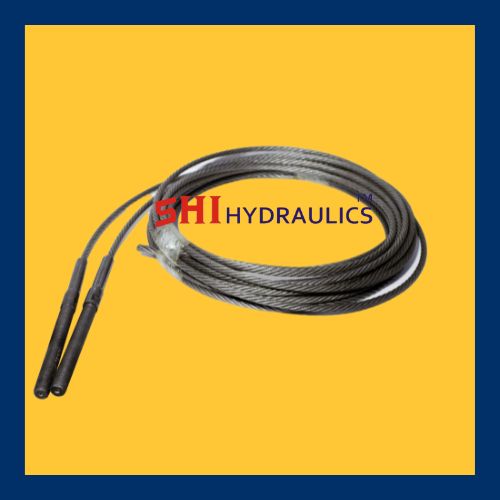
A wire rope is a strong, flexible, and durable cable made from multiple strands of steel or other metal wires twisted together around a central core. It is widely used for lifting, hoisting, towing, and securing heavy loads in industries such as construction, marine, mining, and transportation.
Components of Wire Rope
Wires – Individual metal strands, typically made of steel or stainless steel, providing strength and flexibility.
Strands – Groups of wires twisted together to form the rope’s outer structure.
Core – The central support structure, which can be made of fiber (for flexibility), steel (for strength), or synthetic materials.
Key Features
High Strength – Capable of handling heavy loads and high-tension applications.
Flexibility – Designed to bend around pulleys and sheaves without breaking.
Abrasion Resistance – Some ropes are galvanized or coated for extra protection against wear and corrosion.
Fatigue Resistance – Engineered to withstand repeated bending and stress.
Common Types of Wire Rope
Galvanized Wire Rope – Coated with zinc for corrosion resistance.
Stainless Steel Wire Rope – Highly resistant to rust, ideal for marine and chemical environments.
Compacted Wire Rope – Stronger and smoother due to compressed strands.
Rotation-Resistant Wire Rope – Designed for lifting applications where load twisting must be minimized.
Common Applications
Cranes and Hoists – Used in construction and industrial lifting.
Marine and Fishing – Essential for ship rigging, mooring, and trawling.
Mining and Oil Industry – Used for drilling, winches, and lifting equipment.
Bridges and Suspension Systems – Provides structural support in suspension bridges and cable-stayed structures.
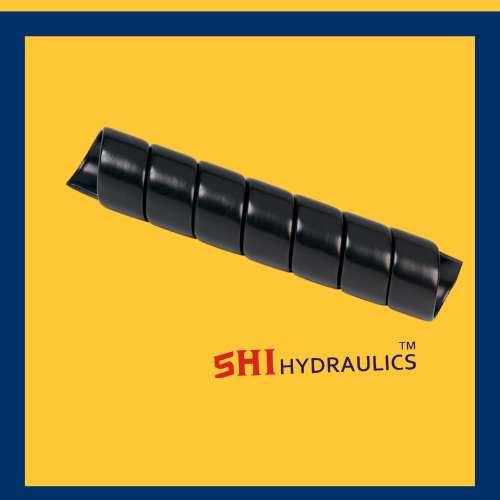
A hose sleeve is a protective covering designed to shield hoses from external damage, abrasion, heat, and environmental factors. It enhances the durability and safety of hydraulic, pneumatic, and industrial hoses used in various applications.
Key Features of a Hose Sleeve
Abrasion Resistance – Prevents wear and tear caused by friction, rough surfaces, or other hoses.
Heat Protection – Some sleeves are made of heat-resistant materials to protect hoses from extreme temperatures.
Flexibility – Allows hoses to bend and move while maintaining protection.
Chemical and UV Resistance – Shields hoses from chemicals, oil, water, and UV radiation.
Easy Installation – Can be wrapped around existing hoses or slid onto hoses during assembly.
Enhanced Safety – Helps prevent hose bursts, reducing the risk of injury and equipment damage.
Common Types of Hose Sleeves
Textile Hose Sleeves – Made from woven nylon or polyester for lightweight and flexible protection.
Spiral Hose Sleeves – Durable plastic or rubber spiral wrap for impact resistance and bundling multiple hoses.
Heat-Resistant Hose Sleeves – Fiberglass or silicone-coated sleeves for high-temperature applications.
Fire-Resistant Hose Sleeves – Designed to withstand fire and extreme heat exposure.
Common Applications
Hydraulic and Pneumatic Systems – Protects hoses in heavy machinery and industrial equipment.
Automotive and Aerospace – Used in fuel and brake lines to prevent abrasion and heat damage.
Construction and Agriculture – Shields hoses from harsh environments and debris.
Oil & Gas Industry – Protects high-pressure hoses from extreme conditions and chemicals.
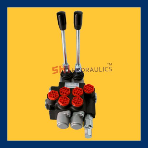
A control valve is a mechanical device used to regulate the flow, pressure, temperature, or level of a fluid (liquid, gas, or steam) within a system. It operates by varying the size of the flow passage in response to a control signal, ensuring precise process control in industries such as oil & gas, power generation, water treatment, and manufacturing.
Key Components of a Control Valve
Valve Body – The main casing that houses the internal components and provides a passage for fluid flow.
Actuator – The mechanism (pneumatic, electric, or hydraulic) that moves the valve to adjust flow.
Valve Plug or Disc – The movable part that regulates the flow by opening, closing, or throttling the passage.
Stem – Connects the actuator to the valve plug for movement control.
Positioner (Optional) – Ensures precise control by adjusting the actuator’s position based on control signals.
Types of Control Valves
Globe Valve – Provides accurate flow control with a linear motion plug.
Ball Valve – Uses a rotating ball with a hole to control fluid flow, offering quick shut-off.
Butterfly Valve – Features a rotating disc for efficient flow regulation in large pipes.
Diaphragm Valve – Utilizes a flexible diaphragm to control flow, ideal for corrosive fluids.
Needle Valve – Designed for fine flow adjustments in small-diameter pipelines.
Pressure Relief Valve – Prevents overpressure by releasing excess fluid when necessary.
Common Applications
Industrial Process Control – Regulates flow and pressure in chemical, power, and manufacturing plants.
Water Treatment – Controls water distribution and filtration processes.
Oil & Gas Industry – Used in pipelines, refineries, and offshore drilling operations.
HVAC Systems – Manages heating, cooling, and ventilation flow rates.
Pharmaceutical & Food Processing – Ensures precise flow control for hygiene and efficiency.
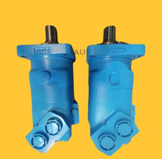
Danfoss is a well-known manufacturer of electric motors, including AC and DC motors, typically used in industrial automation, HVAC systems, and various other applications. Their motors are known for their high efficiency, durability, and compatibility with Danfoss drives and controllers.
Key Features of Danfoss Motors:
High Efficiency: Danfoss motors comply with energy efficiency standards like IE2, IE3, and IE4, ensuring reduced power consumption.
Robust Design: Built for demanding environments, including extreme temperatures, vibrations, and heavy loads.
Compatibility: Designed to work seamlessly with Danfoss VLT and VACON drives for optimal performance.
Low Noise & Vibration: Many models come with noise-reduction technology, making them ideal for noise-sensitive environments.
Wide Application Range: Used in HVAC, water and wastewater management, marine, food processing, and industrial automation.
Advanced Cooling Mechanisms: Some models feature integrated cooling systems for enhanced heat dissipation.
Customizable Options: Available in various power ratings, voltages, and configurations to suit specific industrial needs.
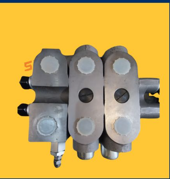
HDD (Horizontal Directional Drilling) valves are specialized components used in drilling operations to control fluid flow, pressure, and drilling mud circulation. These valves play a crucial role in managing the drilling process, ensuring efficient operation and preventing blowouts or fluid loss.
Types of HDD Valves:
Mud Valves – Control the flow of drilling mud, preventing blockages and ensuring smooth circulation.
Check Valves – Prevent backflow of fluids, protecting the drilling equipment from contamination or damage.
Gate Valves – Regulate or shut off fluid flow within the drilling system.
Relief Valves – Prevent overpressure situations by releasing excess pressure in the system.
Ball Valves – Provide quick on/off control of drilling fluids with minimal resistance.
Functions of HDD Valves:
Control drilling fluid pressure and flow.
Prevent drilling mud loss or contamination.
Ensure safe and efficient drilling operations.
Protect the downhole tools and pipeline from excessive pressure.
Gear Pumps
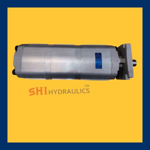
Gear Pump
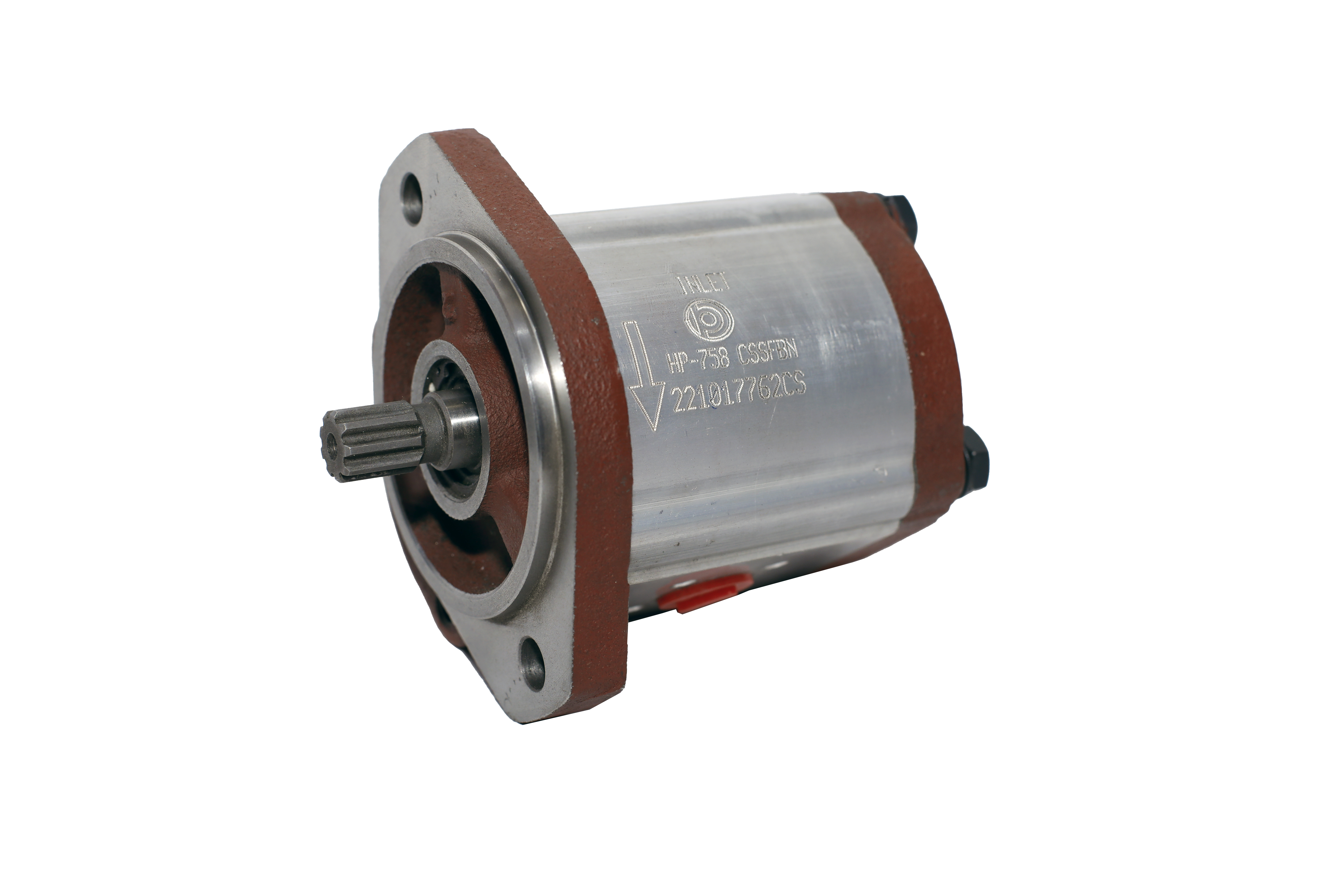
A gear pump is a type of positive displacement pump widely used for transferring liquids in various industrial applications. Known for its simplicity, reliability, and efficiency, the gear pump is a crucial component in many systems, including chemical processing, lubrication, and hydraulic operations. This document provides an in-depth description of gear pumps, including their working principle, components, types, applications, and advantages.
Working Principle
The operation of a gear pump is based on the principle of positive displacement. It consists of two meshing gears that rotate to transfer fluid. As the gears turn, liquid is trapped in the spaces between the gear teeth and the pump casing. This fluid is carried from the suction side to the discharge side of the pump, creating a steady and consistent flow.
Key Components
A typical gear pump comprises the following components:
Gears:
Two primary gears are used—a driving gear and a driven gear.
These gears can be either external (located outside of each other) or internal (one gear inside another).
Pump Housing:
Encloses the gears and maintains alignment.
Designed to withstand high pressures and resist wear and corrosion.
Bearings:
Support the shafts of the gears to ensure smooth rotation.
Often made from materials that minimize friction.
Shafts:
Connect the driving gear to a motor or engine.
Transmit rotational power to the gear mechanism.
Seals:
Prevent fluid leakage and maintain operational efficiency.
Typically made from materials resistant to the pumped fluid.
Types of Gear Pumps
Gear pumps can be categorized based on their design and arrangement of gears:
External Gear Pumps:
Feature two external gears meshing together.
Commonly used for handling low-to-medium viscosity fluids.
Internal Gear Pumps:
Consist of an internal gear that meshes with an external gear.
Capable of handling high-viscosity fluids, making them ideal for applications like oil or syrup transfer.
Lobe Pumps:
A variation where the gears are replaced with lobed rotors.
Gentle on the fluid, making them suitable for food and pharmaceutical industries.
Applications
Gear pumps are versatile and find use across numerous industries:
Lubrication Systems:
Deliver precise amounts of oil or lubricants to machinery and engines.
Chemical Processing:
Transfer corrosive or viscous liquids such as acids, solvents, and polymers.
Hydraulic Systems:
Provide consistent flow and pressure in hydraulic circuits.
Food and Beverage:
Handle thick fluids like chocolate, syrups, and sauces.
Oil and Gas:
Transfer crude oil, refined fuels, and other hydrocarbons.
Medical and Pharmaceutical:
Pump sterile liquids or precise doses of medication.
Advantages
Gear pumps offer several benefits that make them a preferred choice in various operations:
Compact Design:
Small and lightweight, making them easy to install and maintain.
High Efficiency:
Provide consistent flow regardless of pressure variations.
Durability:
Built to handle harsh conditions and abrasive fluids with minimal wear.
Versatility:
Can manage a wide range of viscosities and temperatures.
Self-Priming:
Ability to operate without requiring initial fluid in the pump.
Precise Flow Control:
Deliver accurate and repeatable flow rates, essential in sensitive processes.
Limitations
Despite their advantages, gear pumps have some drawbacks:
Limited Suction Capacity:
Not ideal for pumping fluids over long distances or from deep sources.
Noise:
Can produce higher noise levels compared to other types of pumps.
Sensitivity to Contaminants:
Require clean fluids to avoid gear damage and maintain efficiency.
Fixed Flow Rate:
Flow is directly proportional to the pump speed, making them less flexible in some applications.
Future Trends
The design and application of gear pumps are continuously evolving to meet modern demands:
Improved Materials:
Use of advanced alloys and coatings to enhance resistance to wear and corrosion.
Smart Technology Integration:
Incorporating sensors and IoT capabilities for real-time monitoring and predictive maintenance.
Energy Efficiency:
Developing low-power and energy-efficient designs for sustainable operations.
Customization:
Tailored designs to meet specific industrial needs and regulatory requirements.
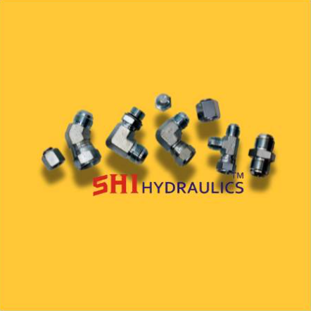
Hydraulic fittings are crucial components in hydraulic systems, connecting hoses, pipes, and tubes to direct and control the flow of hydraulic fluid under high pressure. Designed to ensure leak-proof connections and reliable performance, these fittings play a vital role in maintaining system efficiency, safety, and durability. Used across industries such as construction, agriculture, aerospace, and manufacturing, hydraulic fittings come in various materials, types, and configurations to suit specific applications.
Adaptors
Hose Adaptors
Design and Construction of Adaptors
Hose adaptors are engineered with precision to meet the demands of various systems. Their construction
Materials:
Steel: Ideal for high-pressure and high-strength applications, commonly used in hydraulic systems.
Stainless Steel: Provides excellent resistance to corrosion and is suitable for harsh environments or chemical exposure.
Brass: Known for its corrosion resistance and ease of machining, suitable for medium-pressure systems.
Aluminum: Lightweight and corrosion-resistant, preferred for applications where weight reduction is crucial.
Plastic or Composite: Cost-effective and lightweight, used for low-pressure or non-corrosive environments.
Design Features:
Threaded Ends:
Barbed Connectors:
Quick-Connect Mechanisms:
Swivel Joints: Prevent kinking and reduce stress on hoses by allowing rotational movement.
Sealing Mechanisms:
Types of Hose Adaptors
Hose adaptors are available in various types, each designed for specific purposes. Common types include:
Straight :
Connect hoses or fittings in a straight alignment, maintaining consistent fluid flow.
Elbows:
Feature angled connections, such as 45° or 90°, to accommodate directional changes in fluid routing.
T-:
Allow fluid to split or merge in systems with multiple flow paths, providing flexibility in design.
Reducing :
Enable connections between hoses or fittings of different diameters, accommodating changes in system size.
Swivel :
Allow rotational movement between components to prevent twisting and reduce wear.
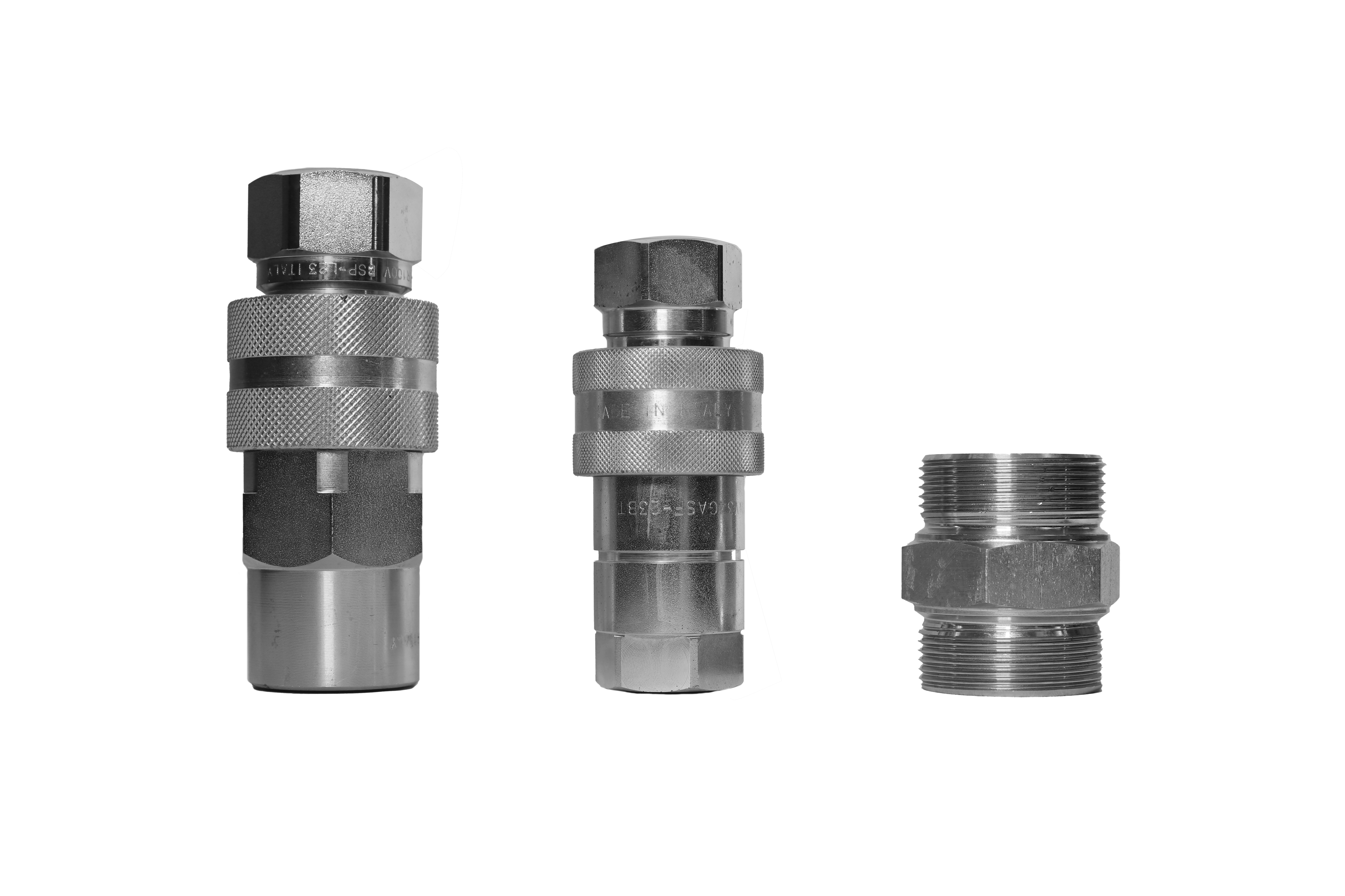
Quick-Disconnect :
Facilitate rapid connections and disconnections, commonly used in systems with frequent maintenance or equipment changes.
Specialized :
Designed for unique applications, such as chemical resistance, high-temperature tolerance, or specific thread patterns.
Applications
Hose adaptors are integral to a broad spectrum of industries and applications:
Hydraulics:
Used in construction machinery, agricultural equipment, and industrial systems to connect hydraulic hoses and components securely.
Pneumatics:
Facilitate air flow in systems such as air compressors, pneumatic tools, and automated machinery.
Automotive:
Commonly used in fuel lines, braking systems, and cooling systems for efficient fluid transfer.
Oil and Gas:
Critical in connecting high-pressure pipelines and hoses in drilling rigs, refineries, and petrochemical plants.
Water Systems:
Employed in irrigation, plumbing, and municipal
Manufacturing:
Used in machinery and equipment to connect hoses for lubrication, cooling, or fluid delivery systems.
Advantages
Hose adaptors offer numerous benefits that enhance the efficiency and functionality of fluid transfer systems:
Versatility:
Available in a wide range of sizes, materials, and configurations to suit diverse applications.
Ease of Installation:
Designed for straightforward installation, often requiring minimal tools or expertise.
Durability:
Engineered to withstand high pressures, extreme temperatures, and harsh environmental conditions.
Leak Prevention:
Precision design and effective sealing mechanisms ensure a secure and leak-free connection.
Customization:
Adaptors can be tailored to meet specific requirements, such as unique thread types or material in compatibility.
Cost-Effectiveness:
Allow the integration of different components without the need for costly system modifications.
Maintenance and Best Practices
To ensure the reliability and longevity of hose adaptors, proper maintenance and handling are crucial:
Regular Inspection:
Check adaptors for signs of wear, corrosion, or leaks. Replace damaged components promptly.
Use Compatible Materials: Select adaptors made from materials that match the fluid type and environmental conditions.
Avoid Over-Tightening:
Excessive tightening can damage threads or compromise the seal.
Protect from Damage:
Shield adaptors from physical impacts, abrasion, and exposure to corrosive chemicals.
Follow Manufacturer Guidelines:
Adhere to installation and maintenance recommendations for optimal performance.
Conclusion
Hose adaptors are indispensable components in.Their diverse range of designs and materials makes them suitable for various industries, from hydraulic systems to automotive and manufacturing applications. By selecting the appropriate adaptor and maintaining it properly, operators can ensure efficient, safe, and reliable operation of
Hydraulic Adaptors
Hydraulic Adaptors Manufacture in Delhi at Sonu Hose Pipe.
Adaptor is a mechanical component designed to connect two incompatible parts, allowing seamless integration in various systems. Adaptors are widely used in hydraulic, pneumatic, electrical, and mechanical applications to modify connections, facilitate compatibility, or improve performance.
Types of Adaptors
Hydraulic Adaptors – Used in fluid power systems to connect hoses, pipes, or fittings with different sizes, threads, or sealing methods.
Pneumatic Adaptors – Allow the connection of air hoses and components with varying diameters or thread types.
Electrical Adaptors – Convert plug types, voltages, or signal formats for compatibility between different devices.
Mechanical Adaptors – Enable the attachment of mismatched shafts, gears, or couplings in machinery and equipment.
Key Components
Body – Typically made from durable materials like steel, brass, aluminum, or plastic, depending on the application.
Threaded Ends or Couplings – Allow secure connections to other components.
Seals and Gaskets – Prevent leaks in fluid or air systems.
Locking Mechanism – Provides stability in high-pressure or high-vibration environments.
Functions & Applications
✔ Size Conversion – Enables the connection of components with different diameters or specifications.
✔ Thread Type Adaptation – Connects male-to-female or metric-to-imperial thread systems.
✔ Angle Adjustment – Provides 90-degree or swivel connections for flexible hose routing.
✔ Material Compatibility – Prevents corrosion or contamination by using the appropriate materials for different environments.
✔ Performance Enhancement – Improves flow rates, pressure resistance, or electrical conductivity.
Industries & Uses
Hydraulic & Pneumatic Systems – In industrial machinery, automotive, and heavy equipment.
Oil & Gas – Used in high-pressure fluid handling applications.
Aerospace & Marine – Ensures secure connections in high-performance environments.
Electrical Engineering – Converts or modifies connections in power and signal transmission.
Advantages of Adaptors
✅ Improves system compatibility and flexibility
✅ Enhances durability and longevity of connections
✅ Reduces downtime and maintenance costs
✅ Provides a reliable and leak-proof connection
✅ Available in various sizes, materials, and configurations
HDD Gear Pump Description
An HDD gear pump is a type of positive displacement pump that uses intermeshing gears to transfer fluids efficiently. These pumps are commonly used in industrial applications where precise fluid movement is required, such as in hydraulic systems, lubrication systems, and chemical processing.
Key Features of HDD Gear Pumps:
High Durability: Made with robust materials like cast iron, stainless steel, or aluminum for longevity.
Efficient Fluid Transfer: Provides a steady and consistent flow without pulsation.
Self-Priming Capability: Can start pumping without requiring external priming.
Handles Viscous Fluids: Suitable for oils, lubricants, and other high-viscosity liquids.
Compact Design: Often used in machinery where space is limited.
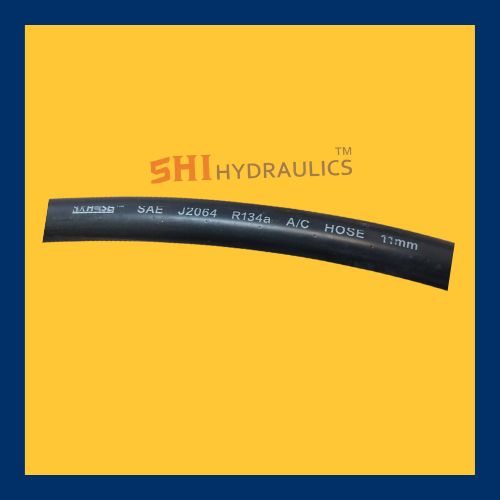
There are different types of AC hose sleeves, such as:
Thermal insulation sleeves – Help reduce heat transfer and improve efficiency.
Braided protective sleeves – Prevent damage from rubbing or external impacts.
Heat-resistant wraps – Shield hoses from high engine or environmental temperatures.
A gear pump is a type of positive displacement pump that moves fluids by using meshing gears to transfer liquid. It is commonly used for pumping oils, fuels, and other viscous fluids.
Types of Gear Pumps
External Gear Pump – Uses two identical gears (driven and driving) to move fluid around the outside of the gears.
Internal Gear Pump – Has a larger outer gear with an internal gear rotating inside it, creating fluid movement.
Working Principle
As the gears rotate, they create expanding cavities on the suction side, drawing fluid in.
The fluid is then carried around the outside of the gears within the casing.
When the gears mesh again on the discharge side, the fluid is pushed out under pressure.
 Chat with us
 Chat with us