Thank you for writing to us. One of our executive will reach back to you through your submitted medium. In case there’s an urgency, feel free to connect over WhatsApp for faster response.
Prefer calling? Dial +919311288288 (International callers) or +919311288288 (Indian callers).
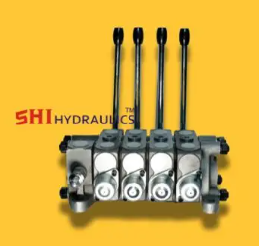
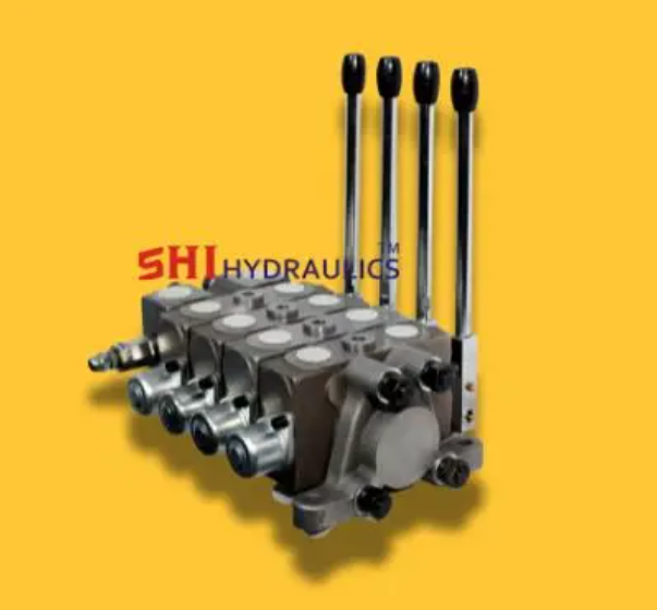
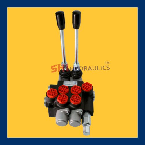
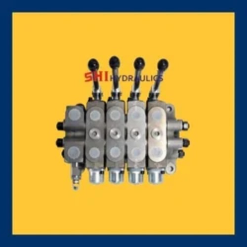
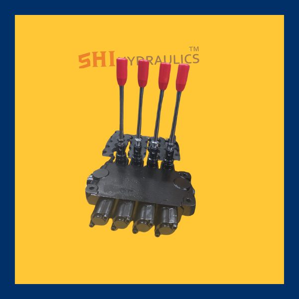
Hydraulic Control Valve
hydraulic control valve is a critical component used in hydraulic systems to control the direction, pressure, and flow rate of hydraulic fluid. The specific valve shown is a multi-spool directional control valve, typically used in mobile and industrial hydraulic equipment.
Key Features:
Multi-Spool Design: Allows independent control of multiple hydraulic functions (e.g., cylinders, motors).
Cast Iron Construction: Ensures durability, high pressure resistance, and a long service life.
Manual/Lever Operation: Operated via levers, which direct hydraulic fluid through different channels based on the spool position.
Pressure Relief Valves: Built-in safety features to protect the system from overpressure.
Multiple Ports: Clearly marked inlet (P), outlet (T), and work ports (A/B) for easy installation and maintenance.
Compact Form Factor: Space-saving design, ideal for mounting in confined areas.
Application: Widely used in agricultural machinery, construction equipment, loaders, cranes, and other mobile hydraulic applications.
Functionality:
Each spool within the valve corresponds to a hydraulic actuator. When a spool is moved, it opens specific internal channels, allowing hydraulic fluid to flow from the pump to a particular actuator, while returning fluid from other actuators back to the tank.
Monoblock Valve: A Comprehensive Overview
A Monoblock valve is a type of hydraulic valve that is designed as a single, compact unit. It plays a crucial role in controlling the flow,
Design and Structure of a Monoblock Valve
The primary characteristic of a Monoblock valve is its monoblock construction, where multiple valve functions
Monoblock valves typically
Valve Body: The main housing that contains the valve’s internal components and channels. It is usually machined from a single piece of metal.
Control Spools or Ball Mechanisms: These components control the flow direction and the opening
Ports: The inlet and outlet ports that allow hydraulic fluid to enter and exit the valve. These ports are typically designed for high-pressure environments.
Spring or Actuator Mechanism: Some block valves are spring-loaded, while others use solenoids or hydraulic actuators to control the valve’s movement and function.
Seals and O-rings: These ensure that there are no leaks between the internal components, maintaining the integrity of the hydraulic fluid system.
Working Principle of a Monoblock Valve
Flow Control: The valve’s internal mechanism, such as a spool or ball,
Pressure Relief: Many monoblock valves include integrated pressure relief features.
Direction Control: Monoblock valves can also control the direction of fluid flow. For example, a directional control valve in a monoblock
Types of Monoblock Valves
Monoblock valves come in various types, each designed for specific tasks within a hydraulic system. The most common types include:
Directional Control Valves:
These valves control the direction of the hydraulic fluid. They are used to change the flow direction,
Flow Control Valves:
Flow control valves regulate the flow rate of the hydraulic fluid in a system. conditions.
Pressure Relief Valves:
These valves are designed to maintain a preset maximum pressure in the hydraulic system. When the system’s pressure exceeds the set limit,
Check Valves:
Check valves allow fluid to flow in one direction only,
Combination Valves:
Some monoblock valves combine multiple valve functions into a single unit, such as a directional control valve with built-in pressure relief and flow control.
Advantages of Monoblock Valves
Compact Design:
One of the primary advantages of Monoblock valves is their compact design. Since all components are integrated into a single unit,
Ease of Installation:
The single-unit design of Monoblock valves simplifies installation.
Cost-Effectiveness:
Monoblock valves are generally more cost-effective than traditional valves that require multiple parts.
Reduced Leak Points:
With fewer parts and integrated construction,
Improved Performance:
The integration of multiple valve functions into a single unit reduces the number of components that could potentially fail,
Applications of Monoblock Valves
Monoblock valves are used in a wide range of applications across various industries, including:
Construction Machinery:
Monoblock valves are used in construction equipment like excavators, loaders, and backhoes to control the movement of hydraulic cylinders and motors.
Agricultural Equipment:
In agriculture, Monoblock valves control the operation of hydraulic systems in tractors, combine harvesters, and other farm machinery.
Industrial Automation:
These valves are widely used in industrial machines and production lines for controlling fluid flow to actuators, which is essential in automation processes.
Mobile Equipment:
Monoblock valves are commonly found in mobile machinery like cranes, forklifts, and material handling systems, where they manage the hydraulic flow for various operations.
Automotive Systems:
Monoblock valves are used in automotive applications, such as power steering systems and lifting mechanisms in heavy-duty vehicles.
Conclusion
Monoblock valves are essential components in hydraulic systems, offering a compact, cost-effective, and reliable solution for controlling fluid flow, pressure, and direction. Their integrated design minimizes installation time
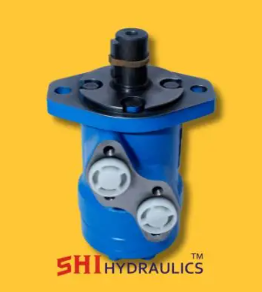
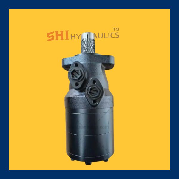
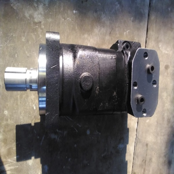
Hydraulics Motors
Hydraulics Motors
is a mechanical actuator that converts hydraulic energy (fluid power) into rotational mechanical energy. It is part of the broader category of hydraulic machinery used in a variety of industrial applications, from manufacturing to construction, where rotary motion is required. Hydraulic motors are powered by pressurized hydraulic fluid supplied by a pump, and they are capable of generating high torque at low speeds, making them essential for demanding tasks
The hydraulic motors operates on the principle of fluid power, which involves the use of pressurized fluid to generate motion. A hydraulic consists of an enclosed rotor or shaft connected to gears, pistons, or other mechanical components,
Pressurized Fluid Inflow: The hydraulic pump sends pressurized fluid to the hydraulic through an inlet port.
Rotational Motion: As the fluid enters the it pushes against the internal components (such as gears or pistons), causing the rotor or shaft to rotate.
Exhaust Flow: Once the fluid has passed through the , it exits via an outlet port, typically at a lower pressure than it entered.
The rotational speed and torque output of the are determined by the pressure of the fluid and the design of the motor itself. Hydraulic motors can produce high
Types
There are several types of hydraulic motors, each designed for specific applications and performance requirements. These include:
Gear:
External Gear These consist of two meshed gears that rotate to generate torque. The fluid is directed between the gears, causing them to spin.
Internal Gear : These have a smaller gear rotating inside a larger gear. They are more efficient than external gear motors and are capable of producing higher torque output.
Vane
These use sliding vanes mounted on a rotor to create pressure chambers as the spins. The vanes push against the walls of the housing, generating rotational motion. V
Piston :
Axial Piston : In these motors, pistons are arranged parallel to the shaft and move back and forth. The fluid forces the pistons to generate motion along the shaft.
Radial Piston Here, the pistons are arranged radially around the motor shaft. These motors are known for their ability to generate high torque at lower speeds,
Rotary Vane
These motors consist of a rotor and vanes that slide in and out to create pressurized chambers. The chambers drive the motor’s
Applications
Construction Machinery: Hydraulic motors are integral to the operation of equipment like excavators, cranes, bulldozers, and wheel loaders,
Agriculture: These motors drive implements such as augers,
Marine and Offshore: Hydraulic motors are used to power winches, thrusters, and other machinery in marine vessels and offshore oil rigs. Industrial Automation:
Automotive: In automotive applications, hydraulic motors are used in systems such as steering, lifting equipment, or as part
High Torque at Low Speeds:
Efficiency:
Compact Design:
Durability and Reliability: T
Precise Control:
Leakage and Fluid Loss:
Noise and Heat Generation:
Maintenance:
Sensitivity to Contaminants:
Vane motors use a rotor with sliding vanes that are forced outward by centrifugal force as the rotor turns. The vanes create pressurized chambers, which generate rotational motion. Vane motors are known for smooth operation and high efficiency, particularly at low speeds, and are often used in applications where quiet and steady performance is required.
Axial Piston Motors: These motors have pistons arranged parallel to the motor shaft. As hydraulic fluid forces the pistons to move back and forth, it causes the motor shaft to rotate.
Monoblock Valve: A Comprehensive Overview
A Monoblock valve is a type of hydraulic valve that is designed as a single, compact unit. It plays a crucial role in controlling the flow,
Design and Structure of a Monoblock Valve
The primary characteristic of a Monoblock valve is its monoblock construction, where multiple valve functions
Monoblock valves typically
Valve Body: The main housing that contains the valve’s internal components and channels. It is usually machined from a single piece of metal.
Control Spools or Ball Mechanisms: These components control the flow direction and the opening
Ports: The inlet and outlet ports that allow hydraulic fluid to enter and exit the valve. These ports are typically designed for high-pressure environments.
Spring or Actuator Mechanism: Some block valves are spring-loaded, while others use solenoids or hydraulic actuators to control the valve’s movement and function.
Seals and O-rings: These ensure that there are no leaks between the internal components, maintaining the integrity of the hydraulic fluid system.
Working Principle of a Monoblock Valve
Flow Control: The valve’s internal mechanism, such as a spool or ball,
Pressure Relief: Many monoblock valves include integrated pressure relief features.
Direction Control: Monoblock valves can also control the direction of fluid flow. For example, a directional control valve in a monoblock
Types of Monoblock Valves
Monoblock valves come in various types, each designed for specific tasks within a hydraulic system. The most common types include:
Directional Control Valves:
These valves control the direction of the hydraulic fluid. They are used to change the flow direction,
Flow Control Valves:
Flow control valves regulate the flow rate of the hydraulic fluid in a system. conditions.
Pressure Relief Valves:
These valves are designed to maintain a preset maximum pressure in the hydraulic system. When the system’s pressure exceeds the set limit,
Check Valves:
Check valves allow fluid to flow in one direction only,
Combination Valves:
Some monoblock valves combine multiple valve functions into a single unit, such as a directional control valve with built-in pressure relief and flow control.
Advantages of Monoblock Valves
Compact Design:
One of the primary advantages of Monoblock valves is their compact design. Since all components are integrated into a single unit,
Ease of Installation:
The single-unit design of Monoblock valves simplifies installation.
Cost-Effectiveness:
Monoblock valves are generally more cost-effective than traditional valves that require multiple parts.
Reduced Leak Points:
With fewer parts and integrated construction,
Improved Performance:
The integration of multiple valve functions into a single unit reduces the number of components that could potentially fail,
Applications of Monoblock Valves
Monoblock valves are used in a wide range of applications across various industries, including:
Construction Machinery:
Monoblock valves are used in construction equipment like excavators, loaders, and backhoes to control the movement of hydraulic cylinders and motors.
Agricultural Equipment:
In agriculture, Monoblock valves control the operation of hydraulic systems in tractors, combine harvesters, and other farm machinery.
Industrial Automation:
These valves are widely used in industrial machines and production lines for controlling fluid flow to actuators, which is essential in automation processes.
Mobile Equipment:
Monoblock valves are commonly found in mobile machinery like cranes, forklifts, and material handling systems, where they manage the hydraulic flow for various operations.
Automotive Systems:
Monoblock valves are used in automotive applications, such as power steering systems and lifting mechanisms in heavy-duty vehicles.
Conclusion
Monoblock valves are essential components in hydraulic systems, offering a compact, cost-effective, and reliable solution for controlling fluid flow, pressure, and direction. Their integrated design minimizes installation time
A control valve is a mechanical device used to regulate the flow, pressure, temperature, or level of a fluid (liquid, gas, or steam) within a system. It operates by varying the size of the flow passage in response to a control signal, ensuring precise process control in industries such as oil & gas, power generation, water treatment, and manufacturing.
Key Components of a Control Valve
Valve Body – The main casing that houses the internal components and provides a passage for fluid flow.
Actuator – The mechanism (pneumatic, electric, or hydraulic) that moves the valve to adjust flow.
Valve Plug or Disc – The movable part that regulates the flow by opening, closing, or throttling the passage.
Stem – Connects the actuator to the valve plug for movement control.
Positioner (Optional) – Ensures precise control by adjusting the actuator’s position based on control signals.
Types of Control Valves
Globe Valve – Provides accurate flow control with a linear motion plug.
Ball Valve – Uses a rotating ball with a hole to control fluid flow, offering quick shut-off.
Butterfly Valve – Features a rotating disc for efficient flow regulation in large pipes.
Diaphragm Valve – Utilizes a flexible diaphragm to control flow, ideal for corrosive fluids.
Needle Valve – Designed for fine flow adjustments in small-diameter pipelines.
Pressure Relief Valve – Prevents overpressure by releasing excess fluid when necessary.
Common Applications
Industrial Process Control – Regulates flow and pressure in chemical, power, and manufacturing plants.
Water Treatment – Controls water distribution and filtration processes.
Oil & Gas Industry – Used in pipelines, refineries, and offshore drilling operations.
HVAC Systems – Manages heating, cooling, and ventilation flow rates.
Pharmaceutical & Food Processing – Ensures precise flow control for hygiene and efficiency.
Putzmeister Agitator Hydraulic Motor – OMH-500
Model No: OMH-500
Application: Concrete Pump Agitator Drive
OEM Part No: 238130001 (commonly associated)
Overview:
The OMH-500 hydraulic motor is a robust and high-torque motor engineered for use in Putzmeister concrete pumps, specifically as the agitator motor responsible for driving the mixing paddle within the hopper. Its primary function is to keep the concrete in constant motion, preventing segregation and ensuring a consistent, pumpable mixture.
Key Features:
�� High-Torque Performance:
Designed with a displacement of approximately 500 cc/rev, the OMH-500 delivers high torque at low speeds—ideal for heavy-duty mixing tasks within the concrete hopper.
�� Smooth Agitation Control:
Supports smooth and continuous rotation of the agitator paddles to maintain a homogenous concrete mix, even with coarse aggregates or varying slump levels.
��️ Heavy-Duty Construction:
Built with reinforced cast iron housing and precision-machined internal components for maximum durability under rugged construction site conditions.
�� Mounting & Fitment:
Standard 4-bolt SAE mounting flange and 35mm splined shaft, ensuring a direct replacement fit for OEM Putzmeister setups.
�� Hydraulic Efficiency:
Designed for low leakage and high volumetric efficiency, contributing to better fuel economy and longer hydraulic component life.
Technical Specifications (Typical):
Parameter Specification
Displacement ~500 cc/rev
Max Continuous Speed 155 RPM
Max Intermittent Speed 200 RPM
Max Torque Output Up to 1,200 Nm
Shaft Type Splined (35mm standard)
Mounting Flange 4-bolt SAE
Port Size G1/2' (BSP or SAE, varies)
Operating Pressure Up to 210–250 bar (approx.)
Fluid Type Hydraulic oil (ISO VG 46/68)
Weight Approx. 20–25 kg
Applications:
✅ Putzmeister Concrete Pumps – Agitator Motor (e.g., BSF, TK, P 718 models)
✅ Suitable for retrofitting or replacing damaged motors in hopper mixer drives
✅ Used in OEM and aftermarket repair of ready-mix and shotcrete pump systems
Benefits:
Prevents Concrete Hardening in Hopper
Continuous mixing action prevents concrete from settling or solidifying during pauses in pumping.
Reduces Maintenance Downtime
Durable design reduces the need for frequent servicing or premature replacement.
Improves Pump Efficiency
Ensures consistent flow of well-mixed concrete, protecting the main pumping cylinders.
HDD Control Valves Control valves** in HDD rigs manage the direction, flow rate, and pressure of hydraulic fluids powering various components, such as:
Thrust/pullback systems
Drill rotation motors
Clamp/vise actuators
Pipe loader arms
Mud pump drive systems
They can be manual, pilot-operated, or electro-hydraulic depending on system complexity.
�� 2. Types of Valves Used in HDD Systems
Valve Type Function Common Placement
Directional Control Valve (DCV) Directs flow to actuators (e.g. extend/retract cylinders) Main hydraulic circuits
Flow Control Valve Regulates speed of actuators by limiting flow Rotation/thrust speed adjustment
Pressure Relief Valve Protects system from overpressure Inline with all major circuits
Pilot-Operated Check Valve Locks actuators in place under load Clamp and rotation holding systems
Solenoid Valve Electrically controlled valve for automated function Remote or onboard controls
Load-Sensing Valve Adjusts flow based on demand, improving efficiency Advanced HDD rigs
⚙️ 3. Features:
High pressure handling (up to 5000 psi / 350 bar)
Compact modular manifolds for integrated control
Stackable for space-efficient designs
Available in cartridge or monoblock forms
Options for manual levers, electric joystick, or remote radio control
�� 4. Specifications (Typical):
Spec Value
Flow Rate 20–150 L/min
Pressure 210–420 bar (3000–6000 psi)
Ports BSP, NPT, or SAE
Control Manual, electric, or hydraulic pilot
Material Steel or cast iron (plated for corrosion resistance)
�� 5. Brands Used in HDD Machines:
Rexroth (Bosch)
Parker Hannifin
Hydac
Sun Hydraulics
Danfoss / Eaton
Walvoil, Yuken, and Atos
�� 6. Applications in HDD Rigs:
System Valve Role
Thrust/Pullback Directional & flow control for hydraulic cylinders
Rotation Drive Speed & torque control via flow/pressure regulation
Clamp/Vise Check valves to hold position under load
Rod Loader Directional valves for actuator motion
Drill Head Steering Fine pressure and flow adjustments for steering nozzles
�� 7. Maintenance & Troubleshooting:
Regularly inspect for leakage, spool stickiness, or overheating
Ensure filters are clean to avoid contamination wear
Check for correct voltage on solenoid coils
Use diagnostic tools to monitor pilot pressure and feedback
HDD Thrust Motor
HDD Thrust Motor a standard or widely recognized component in the architecture of hard disk drives. However, you may be referring to or mixing up terms that are related to actuator movement or spindle mechanics.
HDD Gear Pump, which is a critical component in Horizontal Directional Drilling (HDD) rigs for powering hydraulic circuits.
⚙️ HDD Gear Pump �� 1. What is an HDD Gear Pump?
An HDD Gear Pump is a hydraulic pump that uses the meshing of gears to pump hydraulic fluid through the system. It's used in HDD rigs to drive key hydraulic functions like:
Thrust/Pullback
Drill head rotation
Clamp and vise control
Pipe loader arm
Mud pump drive
These pumps are chosen for their reliability, simplicity, and high-pressure capability.
�� 2. Construction Details:
Component Material Function
Housing Cast iron or aluminum Contains the gear assembly
Gears Steel (surface-hardened) Create suction/discharge action
Bearings/Bushings Bronze or anti-friction steel Support rotating gears
Seals/O-rings Nitrile or Viton Prevent internal & external leakage
⚙️ 3. Working Principle:
Two gears (driving and driven) rotate inside the housing.
Fluid is drawn into the pump at the inlet, carried around the gear teeth in chambers, and pushed out through the outlet.
The tight clearances between components prevent backflow.
�� 4. Technical Specifications:
Parameter Typical Range
Flow Rate 10–150 L/min (2.5–40 GPM)
Working Pressure 150–300 bar (2200–4500 psi)
Displacement 5–60 cc/rev
Speed Range 1000–3500 RPM
Temperature Range -20°C to +100°C
Mounting SAE flange, European standard (2 or 4-bolt)
Drive Keyed shaft or spline
��️ 5. Features & Benefits:
High volumetric efficiency
Simple and robust design
Compact size and easy mounting
Suitable for continuous duty cycles
Low maintenance compared to piston pumps
Handles dirty or abrasive hydraulic oils better than more complex pumps
�� 6. Common Applications in HDD Rigs:
System Pump Role
Drill rotation Powering hydraulic motors for the drill head
Pullback/thrust Moving hydraulic cylinders for pushing/pulling rods
Clamp/Vise system Opening and closing the pipe holder
Mud mixing or pumping (auxiliary) Powering hydraulic-driven mud pumps
�� 7. Top Brands & Models:
Parker Gear Pumps (PGP series)
Eaton/Char-Lynn
Casappa (Kappa or Polaris series)
�� HDD Track Motor – Overview�� Function:
Powers the caterpillar tracks (undercarriage) of an HDD rig.
Allows the rig to move across job sites, especially in rough terrain.
Usually hydraulically driven, controlled via the machine's onboard system.
⚙️ Components:
Hydraulic Motor:
Converts hydraulic fluid pressure into mechanical torque.
Usually a radial piston or orbital motor for high torque at low speed.
Planetary Gearbox:
Reduces speed and increases torque output.
Designed for heavy-duty use in mobile machinery.
Brake System:
Often a built-in spring-applied, hydraulically released brake.
Prevents movement when the machine is idle or off.
Mounting Flange & Sprocket:
Connects directly to the track sprocket, enabling motion transfer to tracks.
✅ Key Features:
High torque output
Compact design for integration into the track frame
Sealed and weather-resistant for outdoor use
Built for shock loads and heavy-duty cycles
�� Applications:
Horizontal Directional Drilling Rigs (Vermeer, Ditch Witch, etc.)
Pipeline and trenchless installations
Other crawler-based construction machinery
�� Specifications (typical range):
Spec Value
Flow Rate 60–200 L/min
Max Pressure 300–450 bar
Torque 3000–15000 Nm
Speed Range 0–50 RPM
If you need:
A part number cross-reference (for a brand like Vermeer or Ditch Witch)
A spare parts diagram
Hydraulic circuit showing the track motor's role
Or help identifying one from a machine
 Chat with us